NOOR ALAM Online Technical Services

Pakistan Ist online technical Services Provider

NOOR ALAM Online Technical Services

Pakistan Ist online technical Services Provider

NOOR ALAM Online Technical Services

Pakistan Ist online technical Services Provider

NOOR ALAM Online Technical Services

Pakistan Ist online technical Services Provider

NOOR ALAM Online Technical Services

Pakistan Ist online technical Services Provider .

NEWS UPDATES
Welcome to NOOR ALAM's Online Technical solution we're provides Mechanical Electrical Instruments Civil online Services ,and many many more:

Sunday, December 18, 2016

ABOUT NOOR TECH


Saturday, December 17, 2016

The Snamprogetti Urea Process Description

The Snamprogetti Urea Process Description

The Snamprogetti Urea Process is basically a total recycle stripping process using ammonia as self stripping agent. The Snamprogetti process used the excess ammonia present in the urea solution leaving the reactor to strip CO2 from urea solution in a falling film steam heated heat exchanger operated at the urea reactor pressure. The separated CO2 and NH3 are recombined as ammonium carbamate in the carbamate condensers, also operating at urea reactor pressure and then returned to the reactor for conversion to urea.

The overall result of this scheme is that an internal recycle of both NH3 and CO2 in the urea reactor system is established without having to pump either component , as in previous total recycle process in which NH3 and CO2 were separated from the solution at lower pressure. This substantially reduces the high pressure pumping requirements for both the NH3 and ammonium carbamide solution, since in the Snamprogetti stripping process approximately 80% of the CO2 fed is converted to urea within high pressure synthesis loop and only about 20% of it must be pumped back to the reactor as ammonium carbamate solution from lower pressure. In addition to the reducing pumping requirements, this process permits a substantial saving in steam requirement, since the operating temperature level of the ammonium carbamate condenser by utilizing the heat released by the condensing vapor.

The NH3 to CO2 ratio used in Snamprogetti process is 3.3-3.6 : 1which combines with a temperature of 186-189deg C and pressure of 155 Kg/cm2g approximately, permits a conversion yield in the reactor of 62 to 65%. Plant layout

Block diagram of total recycle of ammonia stripping in urea production:

Block diagram of total recycle ammonia stripping urea process


Urea production takes place through the following main operations:
  • Urea synthesis and high pressure recovery.
  • Urea purification in the medium, low pressure decomposers, pre-vacuum concentrators. Urea concentration.
  • Urea Prilling.

The liquid ammonia coming from the battery limit at a temperature of 12oC and 18 Kg/cm2(g) is collected in a ammonia receiving vessel which is operated at a medium pressure(17Kg/cm2). From the ammonia receiver, the liquid ammonia is pumped to the reactor by two pumps. The first pump is the ammonia booster pump which is centrifugal type and supplies the liquid ammonia at 22Kg/cm2 to second pump suction. The second pump is the high pressure ammonia pump which is a reciprocating-plunger type. Due to the reciprocating motion of second pump pulsating takes place in the discharge of booster pump and those cause the change of loads on booster pump to avoid these booster pump and those cause the change of loads on booster pump to avoid these pulsations a damper is provided in the suction of second pump. In the H.P. ammonia pump, the ammonia pressure is increased to 239Kg/cm2 and then goes to a ammonia pre heater where it is preheated to 75oC by L.P. decomposer outlet gases, H.P. ammonia is used as pressure section contains first and second stage another one is the high pressure section contains third and fourth stage. First and second stages contains three, third stage contains four and fourth stage two numbers of closed type impellers. Carbon dioxide gas enters first stage suction at 1.5kg/cm2 and 40oC and compressed to 160 Kg/cm2 in four stages. Intercoolers are provided after first, second and third stages to cool the carbon dioxide using cooling water. Along with coolers knock out drums are provided between each stage in which moisture gets separated. Lube oil system provides the lubrication of the rotating parts. The superheated steam and saturated LS steam is used as a driving fluid for steam turbine. Superheated HS steam is extracted and part of steam is condensed in condenser. Condensate is then pumped to D.M. plant.


detail flow sheet of urea prilling tower system
Flow sheet of
Urea prilling system

Block diagram for urea granulation and prilling process
Block diagram of
urea prilling section


Block diagram of total recycle carbon dioxide stripping urea process


Block diagram of total recycle of carbon dioxide stripping in urea production

NITRIC ACID Production Process

NITRIC ACID Production Process


Properties of NITRIC ACID


1. Appearance Colorless to yellowish liquid
2. Odor Suffocating, acrid
3. Solubility Infinitely soluble
4. Molecular weight 63.013
5. Boiling point 86°C
6. Viscosity 1.62cp
7. Density (60% conc.)
  • 0°C 1.3931Kg/m3
  • 25°C 1.36 Kg/m3
  • 100°C 1.2547 Kg/m3
08. Melting point -42°C
09. Specific gravity 1.502
10. Critical temperature 520°K
11. Critical pressure 68.9 bar
12. Critical volume 145 cm3/mol
13. Diffusivity in the water 2.9X10⁻⁵ cm2/s
14. Vapor Density (Air=1) 2-3 Kg/m3
15. Vapor Pressure (mm Hg) 48 @ 20°C (68 °F)
16. Specific heat (20°C) 0.64 cal/g

Classification of Nitric Acid Production Processes:

1. Ammonia oxidation process (Ostwald’s process)
2. NaNO3 +H2SO4 process (Chile Salt Peter process)
3. N2 fixation from air (Wisconsin process)
4. Nitrogen fixation by nuclear fission fragments
OSTWALD PROCESS

Reactions involved in the Ostwald’s process
Main reactions
1.       Oxidation of NH3 to NO
        NH3+5/4O2 NO+3/4H2O        ∆H= -54Kcal
2.       Oxidation of NO to NO2
        2NO+O  2 NO2                  ∆H= -27.2Kcal
3.       Absorption of NO2 in water
        2NO2+H2  HNO3 +HNO2
4.       Concentration of HNO3 
Side reactions 
       NH3+3/4O  1/2N2+3/2H2O      ∆H =-75.7Kcal
       NH3                 1/2 N2 +3/2H2
       NH3+O2            1/2N2 O+3/2H2O
       NH3+3/2NO      5/4N2 +3/2H2O    ∆H= -107.9Kcal

ostwald nitric acid production flow sheet,Nitric acid production from ammonia,process description of nitric acid production
Nitric acid production flow sheet (Ostwald’s process)
Process Description:
Raw materials required for manufacture of nitric acid
a. Anhydrous Ammonia
b. Filtered air
c. Platinum –Rhodium  catalyst
d. Water

Anhydrous Ammonia 
In 1909 Fritz Haber established the conditions under which nitrogen, N2 (g), and hydrogen, H2 (g), would combine at the conditions:
        Medium temperature (~500 degC)
        Very high pressure (~250 atmospheres, ~351kPa)
        A catalyst (a porous iron catalyst prepared by reducing magnetite, Fe3O4).
Osmium is a much better catalyst for the reaction but is very expensive. This process produces an ammonia, NH3 (g), yield of approximately 10-20%. The Haber synthesis was developed into an industrial process by Carl Bosch. The reaction between nitrogen gas and hydrogen gas to produce ammonia gas is exothermic, releasing 92.4kJ/mol of energy at 298°K (25degC).

Platinum-Rhodium catalyst
Properties of platinum
  •  Atomic number:- 78
  •  Atomic weight:-195.09g./mol
  •  Density:-21.45gm/cm3
  •  Melting point:-1769°C
  •  Boiling point:- 3827°C
  •  Thermal conductivity :-73 Watt/meter/°c
  •  Tensile strength:- 14kg/mm2
  •  Isotopes:-6
  •  Electrical resistivity:- 9.85 micro hg.cm at°C

Chemical properties
 It has the third highest density behind osmium and iridium
 Platinum is unaffected by air and water but will dissolve in hot aqua regia, in hot concentrated phosphoric and Sulphuric acid in the molten alkali
 It is as resistant as gold to corrosion and tarnishing. Indeed, platinum will not oxidize in air no matter how strongly it is heated.

Properties of Rhodium
 Rhodium is silver white metal
 Melting point:-1966°C
 Boiling point:-4500°C
 Density:- 12.41 gm/cm3

Special properties
 High electrical and Heat conductivity. That means heat and electricity pass through rhodium easily
 Chemical properties
 Is relatively in active metal. It is not attacked by the strong acids. When heated in air, it is combined slowly with O2.

Main components involved in the process are:

  •  Kobe air compressor
  •  Secondary air compressor – 1and 2
  •  Instrument air compressor-A,B
  •  Air drying unit
  •  Air receiver
  •  Silica gel for dry air
  •  Turbine
  •  Catalytic converter
  •  Air-heater
  •  Oil separator
  •  Ammonia evaporator
  •  Ammonia super heater
  •  Air – ammonia mixer
  •  Mixed gas filters -1 and 2
  •  Waste heat boiler (W.H.B)
  •  Deaerator
  •  Tail gas heater -1,2 and 3
  •  Boiler feed water (B.F.W)
  •  Start acid up tank
  •  Absorption tower
  •  Bleaching tower
  •  Product acid cooler
  •  Storage tank


Air Compressor and Turbine:
Air from atmosphere is suck at ambient temperature (room temperature) into the compressor. The compression is done in three stage driven by electric motor and turbine which is in turn run by tail gases .The air first passes through 1st stage at room temperature and leaves at temperature of 130°C and pressure of 2.02kg/cm2.This is then cooled in the inter cooler to 55°C by using raw water as cooling medium. Then air enter the second stage where it is compressed to 3.5kg/cm2 and temperature of 118°C and after the second stage is cooled to 70°C in the inter cooler then it enters the third stage where it is compressed to 4.5kg/cm2 abs and outlet temperature of 143°C. 40% of the energy required for carrying out compression operation is supplied by tail gas turbine. These tail gases are generally taken from absorption tower which leave at 19°C.it is heated up to 260°C by the series of heat exchangers. Major amount of air which is called as a primary air is sent to Air-heater.

Secondary Air Compressor-1, 2:
The secondary air which is supplied by secondary air compressor-1, 2 used is in the bleaching tower

Air-Heater:
The air from the compressor enters the air-heater at 143°C and there it is further heated to 208°C by using high pressure steam and leaves at 208°C.

Ammonia Evaporator:
The liquid ammonia stored in ammonia bullets is sent to the evaporator at 10-12kg/cm2 through tube side and 21°C temperature, where it is vaporized by the chill water coming from the absorption tower passing through shell side. The ammonia leaves the evaporator at 19°C.

Ammonia Super Heater:
The ammonia which enters the super heater is further heated to 80°C by using low pressure steam. Here the shell side flow is ammonia and the tube side flow is low pressure steam.

Ammonia-Air Mixture:
Ammonia enters the mixer at 80°C and air at 208°C and mixing takes place and heat is exchanged between them and leaves at 180°C. proportion of Ammonia and Air is10-10.7.

Mixed Gas Filter 1, 2:
Mixed gas filters consists of “SS –candle” as filter medium. The air –ammonia mixer enters this filter in order to remove the impurities present in the mixture. Presence of the impurities in the mixture may corrode the catalyst surface.

Waste Heat Boiler:
At the entrance of the waste heat boiler the mixture may be around 180°C. Here the hydrogen flame is used to raise the temperature. This waste heat boiler consists of platinum-rhodium catalyst for the reaction to start. First it consists of supporting bars on which the nichrome mesh is placed, above which the palladium catchment gauge is placed and finally the platinum (95%)-rhodium (5%) catalyst is placed. The reaction is carried at 850°C. At the bottom part of the waste heat boiler which is in the form of cylinder, consists of tubes in which the NOX gases flow and on shell side boiler feed water is supplied for cooling the NOX gases. The heat that which is produced by the NOX gases is gained by the boiler feed water and high pressure steam is generated. This high pressure steam is sent to steam generation station where it is split into low pressure, medium pressure and high pressure steam. They are utilized in some parts of the plant. Here the rich gases is sent into the tail gas heat exchanger III and the lean gases is sent into tail gas heat exchanger-II

Tail Gas Heat Exchanger-II:
Tail gas heater –II is a shell and tube heat-exchanger in which the nitrous gas is passed through shell side which enters at 320°C and leaves at 280°C and tail gas (coming from T.G.H-I) is passed through tube side which enters at 160°C and leaves at 250°C. The tail gases are sent to catalytic converter and the nitrous gases are sent to boiler feed water.

Boiler Feed Water:
Here de-mineralized water which is de-aerated by steam and sent through tube side is used for cooling the nitrous gas passing through shell side. The inlet temperature of the nitrous gas is 280°C and outlet 180°C. The outlet steam is sent into waste heat boiler. The nitrous gas is further sent to T.G.H-I.

Tail Gas Heater-I:
Tail gas heater –I is a shell and tube heat-exchanger in which the nitrous gas is passed through shell side which enters at 180°C and leaves at 155°C and tail gas (coming from Tail gas pre-heater) is passed through tube side which enters at 45°C and leaves at 160°C. The tail gases are sent to catalytic converter through T.G.H-II and the nitrous gases are sent to condenser.

Cooler Condenser:
The nitrous gas from T.G.H-I is sent to the shell side of the cooler condenser and the cold water from the VAM unit is circulated on the tube side. The nitrous gas enters the cooler condenser at 155°C and leaves at 56°C.The cooled water is recycled and the nitrous gas is sent the adsorption tower.

Absorption Tower:
This tower consists of 69 trays in which 64 trays are absorption trays and the 5 trays are oxidation trays. The nitrous gas are first sent to oxidation trays there nitrous gas converted into NO2 and then it is sent into the absorption trays in which the De-mineralized is sprayed from top and the NO2 gets converted into HNO3 (nitric acid). Then it is finally sent to bleaching tower. The tail gases are sent to tail gas pre-heater

Tail Gas Pre-Heater:
The tail gas from the absorption tower is sent to the tail gas pre-heater in which the tail gases are heated by using low pressure steam. The tail gas enters the tail gas pre-heater at 19°C and leaves at 45°C. The outlet tail gas is sent to new tail gas heater-III and also to T.G.H-I.

New Tail Gas Heater-III:
The rich gases from the waste heat boiler are circulated on shell side of the new tail gas heater-III. This enters at 320°C and leaves at 160°C. The tail gas from the tail gas pre-heater is circulated on tube side. This enters at 45°C and leaves at 285°C. Finally the tail gas from the tail gas per-heater-III is used to run the turbine.

Bleaching Tower:
The secondary air from the secondary air compressor is supplied to the bleaching tower to remove the color of the nitric acid.

Product Acid Cooler:
The nitric acid thus obtained is cooled by using the cooling water in the product acid cooler. Then it is finally sent to the storage tank-A, B

Catalytic Convertor:
Tail gases from the T.G.H-II are sent to catalytic converter and the vapor ammonia is also fed from NH3 super heater.
NO + NO2 +2NH3 2N2 + 3H2O
Here tail gases and ammonia reacts with each other and forms nitrogen and water vapour. This can then be safely disposed to atmosphere

NITRIC ACID PRODUCTION FROM CHILE SALT PETER  PROCESS:

NaNO3 + H2SO4        NaHSO4 + HNO3

Reactor for Urea Production and Urea Process Parameters


diagram of low pressure decomposer used in continuous production of urea in large scale
Low Pressure Decomposer
line diagram of urea production at low pressure section
Diagram of Low Pressure
Urea Section


A complete urea process description with flow sheet

Brief equipment design of a reactor for producing 2100 MTPD of Urea:

Internal trays :


Sieve trays            : 480 holes 8 mm diameter, equispaced triangular pitch
Number of trays : 15 equispaced , 666.67 cm diameter


Feed distribution nozzle : 


CO2 inlet 265 holes of 8 mm diameter
NH3 inlet 440 holes of 8 mm diameter
Operating/ Design temperature 188/210oC
Operating/ Design pressure 155/170 Kg/cm2 g
Design pressure 170 Kg/cm2 g
Joint efficiency = j 0.85
Allowable stress = f 22.5 Kg/cm2 g
Capacity 2100 MTPD
Density of NH3/CO2 at 188oC 881.5387/809.29 Kg/m3


Concentration Vs Rate of reaction data for carbon dioxide:

Concentration
CA, Kgmole/m3

18.39

16.55

14.71

12.87

11.03

9.19

7.35

5.51
Rate of reaction, -rA
Kgmole/hr m3

27.05

21.92

17.31

13.25

9.74

6.76

4.33

2.43


Calculation:                                                                                       

 Ï„/CAo  =  V/fAo  =  ΔXA/ -rA

From material balance :
fAo = 2278.645 Kg mole/hr
CAo  = fAo /Vo
Vo = (inlet flow of CO2)/(Density of CO2) = 100260.42 / 809.29 = 123.886 m3/hr
CAo  = 2278.645/123.886 = 18.39 Kg mole/m3


Plotting graph (1/-rA) Vs CA :
Concentration
CA Kgmole/m3
18.39 16.55 14.71 12.87 11.03 9.19 7.35 5.51
Rate of reaction  -rA
Kgmole/hr m3
27.05 21.92 17.31 13.25 9.74 6.76 4.33 2.43
        1/-rA 0.037 0.046 0.058 0.075 0.102 0.148 0.231 0.411


From graph :

Area = 137.8×2×0.02 = 5.512 hr
Area = Ï„ = 5.512 hr
Now V = Ï„× fAo/CAo
V = (5.512×2278.65)/18.39 = 682.974 m3
Assuming height to be 18 meters
V = pi R2
R2 = (683)/(Ï€×10) = 12.075m2
R = 3.475 m
Diameter = 6.95 m

Types of Agitators

Types of Agitators


propeller agitator and free calculator for power consumptionPropeller agitators are commonly made of three bladed attached to the main shaft. They are flexible in operations and mostly used in mechanical mixing of low to medium viscosity fluids. These type of propellers are also called as marine type propellers. The diameter of the propellers depends on the rotational speed and diameter of the batch reactor or the agitator vessel. Depending on the agitator vessel size and the fluid viscosity the power consumption of the propeller agitator may exceed more than 50kW.                         
turbine impeller and mixing intensity calculatorpitched turbine Turbine impellers operate at low speed and are much larger than propellers. Turbine has an excellent feature in designing the flow patter where a change in design can divert the flow pattern of fluid by radial flow or axial flow in the reactor vessel. Based on the configuration of the impeller blades these flow patterns can be achieved. Radial design make the fluid to flow at high velocity in radial direction where as axial impellers use pitched blades, make the fluid to flow parallel to shaft in downward direction and then push the fluid towards the wall of the agitator vessel. For gas dispersion operation radial turbine impeller is used and axial turbine impeller is used for chemical reactions, suspension solid and miscible liquid mixing. 
anchor type agitator and a calculator for calculating power and mixing requirement

Types of agitators models, application and comparison:

Agitator models Application Advantages Disadvantages
Paddle:
  • Flat paddles
  • Finger paddles
  • Gate paddles
  • Solid mixing
  • Slurry mixing
  • Heavy duty mixing
  • Adjustable to 2 or 4 blades
  • Excellent for low speed
  • High power consumption
  • Inefficient liquid circulation
Counter rotating paddles Paste mixing
  • Efficient in laminar condition
  • Blending
  • Vibrates at high speed
  • Not suitable for liquid mixing
Tumbling Blending Paste and viscous material mixing Not suitable for  fluid solutions
Disk and cone Polymers and dispersion preparation Viscous solution mixing with 60 revolution per second Paste mass cannot be handled
Free shaft suspension Sugar processing Suspension, Thickening operation High power requirement
Impeller type Emulsion preparations
  • Good temperature control
  • Creates axial flow
  • Good phase mixing
Not for viscous materials
Turbine agitator
  • Straight blade
  • Pitched blade
  • Vaned disk
  • Curved blade
Liquid and gas reactions
  • Excellent for dispersion operations
  • Creates good radial flow
Only for less viscous liquid below 15 to 20 Ns/m2
Slotted rotary
  • Rotating disk
Powders and
cosmetics
Unique particle size and homogeny product formation
  • Minimum axial flow
  • Operates better only for 0.1 to 0.01mm particle size solids
Screw
  • Screw in cone
Food and snack processing Homogenization of high viscous materials Not suitable for miscibility operations
Helical
  • Ribbon type
  • Helical screw
Polymer and paints processing Handles viscoelastic liquids that are more than 20 Ns/m2 Less radial flow patterns
Gate Blending operations
  • Good speed control
  • Handles pseudoplastic liquids
Not for suitable for gas to liquid operations
Anchor
  • Round anchor
  • Combine anchor and gate
Milk and fat processing Efficient heat exchange between the reactor walls and reaction mass (fluids)
  • High power consumption
  • Requires heavy duty gear box
Propeller
  • Dairy and food processing
  • Chemicals processing
  • Less  Metzner –Ott shear rate constant
  • Homogenization
  • Good miscibility
  • Motion of liquid starts on one spot
  • Dead spots formation at high rotation speeds
  • Occurrence of solids settling at low speeds

Industrial agitators

Industrial agitators are machines used in industries that process products in the chemical, food, pharmaceutical and cosmetic industries, in a view of :
  • mixing liquids together
  • promote the reactions of chemical substances
  • keeping homogeneous liquid bulk during storage
  • increase heat transfer (heating or cooling)
They are devices used to stir or mix fluids, liquids specifically.

Types

Mainly 4 types of Agitators are used in Pharmaceutical reactors, they are
1.Anchor
2.Turbine
3.Propeller
4.Gas induction

Several different kind of industrial agitators exist:
  • mechanical agitators (rotating)
  • static agitators ( pipe fitted with baffles)
  • Rotating tank agitators (like concrete mixer)
  • Agitator Mixer Padole Type
  • Agitators working with a pump blasting liquid
  • Agitator turning thanks to gas
The choice of the agitator depends on the phase that needs to be mixed (one or several phases): Liquids only, liquid and solid, liquid and gas or liquid with solids and gas. Depending on the type of phase and viscosity of the bulk, the agitator can be named mixer, kneader, dough mixer, amongst others. The agitators use in liquids can be placed on the top of the tank on vertical position, or horizontally (on the side of the tank) or less common, agitator is located on the bottom of the tank.

Principle of agitation

The agitation is achieved by movement of the heterogeneous mass(liquid-solid phase),to the impeller. This is due to mechanical agitators, to the rotation of an impeller. The bulk can be composed of different substances and the aim of the operation is to blend it or to improve the efficiency of a reaction by a better contact between reactive product. Or the bulk is already blended and the aim of agitation is to increase a heat transfer or to maintain particles in suspension to avoid any deposit.

Data of an agitator

The agitation of liquid is made by one or several agitation impellers. Depending on its shape, the impeller can generate:
  • the moving of the liquid which is characterized by its velocity and direction.
  • Turbulence which is an erratic variation in space and time of local fluid velocity.
  • Shearing given by a velocity gradient between two filets of fluids.

These two phenomena provide energy consumption.

Impellers

Propellers (marine or hydrofoil) give an inlet and outlet which are on axial direction, preferably downward, they are characterized by a nice pumping flow, low energy consumption and low shear magnitude as well as low turbulence.
Turbines (flat blades or pitched blades) which inlet flow is axial and outlet flow is radial will provide shearing, turbulence and need approximately 20 time more energy than propellers, for the same diameter and same rotation speed.

Mechanical features

An agitator is composed of a drive device ( motor, gear reducer, belts…), a guiding system of the shaft (lantern fitted with bearings), a shaft and impellers .
If the operating conditions are under high pressure or high temperature, the agitator must be equipped with a sealing system to keep tightened the inside of the tank when the shaft is crossing it.
If the shaft is long (> 10m), it can be guided by a bearing located in the bottom of the tank (bottom bearing).

WHAT IS BOP

This is an Overview about annular BOP (Hydrill).


Here, I am showing the description of hydrill and its parts by images.


this is the image that shows the internal building of hydrill,


and this is another model for annular


· Using a spherical rubber sealing element.
· Low one-piece height to save installation space.
· Large volume of spherical rubber sealing element, long service life.
· Wide sealing range, BOP can seal different sizes and shapes of pipe string, drill tools and wireline/cable not more than BOP bore size in diameter.
· Quick and reliable hydraulic drive.


another type of BOP


Rotary BOP
The rotary blowout preventer (BOP) is used in balanced drilling, negative pressure (underbalance) drilling, counter circulation drilling and well drilling operation by using air, natural gas or foam as circulating medium as well as well servicing operation.
The self-sealing rubber sealing element can ensure that the rotary workover operation or the tripping in/out the pipe string operation with pressure borne is made under maximum kinetic pressure conditions.

MECHANICAL GOVERNOR


Diesel Fuel Systems

Mechanical Governors
This Meeting Guide is the third in a series dealing with the basic
diesel engine fuel system and components. It is about the diesel
governor.

Fig. 01

Each Caterpillar diesel engine is equipped with a governor. Why?
Diesel engines can accelerate-increase speed-at the rate of more
than 2000 revolutions per second. Yes, PER SECOND. Without a
governor a diesel engine can quickly destroy itself.
Fig. 02

GOVERNORS

Never operate a diesel engine without a governor controlling it. If
you were to move the fuel rack of a diesel engine to the full “ON”
position without a load and with the governor not connected, the
engine speed might climb and exceed safe operating limits before
you could shut it down. One second...two seconds...before you
knew what was happening, the engine may have been seriously
damaged by overspeeding.
This warning - never operate a diesel engine without a governor
controlling it - is concerned with one of the purposes of governors:
to prevent engine overspeeding. Governors also keep the engine at
the desired speed and increase or decrease engine power output to
meet load changes.

WARNING
Fig. 03

This presentation introduces and explains the mechanical governor.
The mechanical governor is the simplest of the various types of
governors and is basic to their operation.
Besides the mechanical governor, Caterpillar engines use: servomechanical
governors, hydraulic governors and electronic
governors. These governors will be discussed in future
presentations.

MECHANICAL
Fig. 04

This tractor is equipped with a mechanical governor. We can see the
governor control lever, the control linkage, the governor and the fuel
injection pump housing.

Fig. 05.
This is a closeup of the governor, mounted on the rear of the fuel
injection pump housing.

Let’s look at the construction and operation of the mechanical
governor using schematic illustrations.

Fig. 06

Diesel engine mechanical governors consist of two basic
mechanisms: the speed measuring mechanism and the fuel changing
mechanism.

Fig. 07
The speed measuring mechanism senses engine speed changes, and
the . . . .
Fig. 08

. . . fuel changing mechanism increases or decreases the amount of
fuel supplied the engine to correct these changes.
Let’s look at each basic mechanism separately and learn how it
operates.

Fig. 09
The speed measuring mechanism is simple, has few moving parts
and measures engine speed accurately. The main parts are:
1) gear drive from the engine,
2) flyweights, and
3) spring.

Fig. 10

The flyweights and “L” shaped ballarms which pivot are mounted
on the governor drive.

Fig. 11

The flyweights are rotated by the engine.

Fig. 12

As the flyweights rotate, they exert a centrifugal force outward. The
flyweights move outward pivoting the ballarms upward. The amount
of outward force depends on the speed of rotation.
Centrifugal force is the basic operating principle of the speed
measuring mechanism. Now, what is centrifugal force?

Fig. 13
If we tie a ball on a string . . . .

Fig. 14

. . . . . and swing it around and around . . .

Fig. 15

faster and faster, an outward force-centrifugal force- is exerted on
the ball. This centrifugal force swings the ball outward and upward
until the ball is nearly straight out.
And, we can see that the faster we swing it, the greater the pull on
the string and the farther outward it swings.

Fig. 16

This force - centrifugal force - is the basic principle used in the
speed measuring operation of the diesel engine governor. Keep
centrifugal force in mind as we discuss the other parts of the speed
measuring mechanism. Remember, the greater the engine speed, the
greater the centrifugal force and, therefore, the greater the
movement of the flyweights and ballarms.

Fig. 17

We need to control this centrifugal force, so we have the governor
spring. The spring acts against the force of the rotating flyweights
and tends to oppose them. The force exerted by the spring depends
on the governor control setting.

Fig. 18

A lever connected to the governor control pushes on or compresses
the spring. The spring force opposes the flyweights to regulate the
desired engine speed setting.
The governor control, shown here as a simple push-pull knob, may
be a hand operated control lever or a foot operated accelerator
pedal.

Fig. 19
As long as the spring force equals the flyweight centrifugal force,
engine speed remains constant.

Fig. 20

The speed measuring mechanism, then, senses and measures engine
speed changes. The fuel changing mechanism links the speed
measuring mechanism with the fuel injection pumps to control
engine.

Fig. 21

The fuel changing mechanism consists of the:
1) connecting linkage,
2) rack and
3) the fuel injection pump.

Fig. 22

Flyweight movement - outward in this example - due to engine
speed changes, are transferred through the simple linkage to the
rack and, therefore, to the fuel injection pump plunger.

Fig. 23

When the engine load increases - as when a dozer digs in - the
speed decreases. The flyweight force decreases, and the spring
moves the linkage and rack to increase the fuel to the engine. The
increase fuel position is held until the engine speed returns to the
desired setting, and the flyweight force again balances the spring
force.

Fig. 24

When the engine load decreases, the speed increases. The flyweight
force increases, overcoming the spring force, moving the rack to
decrease fuel to the engine. The decrease fuel position is held until
engine speed returns to the governor control setting, and the spring
force again balances the flyweight force.

Fig. 25

In summary, the basic governor consists of the:
drive gears, flyweights, spring, and control lever of the speed
measuring mechanism, and the connecting linkage, rack and fuel
injection pump of the fuel changing mechanism.

Fig. 26

The rack which meshes with the injection pump plunger gear
segments extends from the injection pump housing into the
governor. The rack and fuel injection pumps are parts of the fuel
injection pump housing assembly.

Fig. 27

As you recall, Meeting Guide 43, Fuel Systems: Part 2, explained
fuel injection pump operation and how the fuel injected into each
cylinder is increased or decreased.

Fig. 28

In this cutaway governor and fuel injection pump housing, we see
that the rack extends into the governor. Rack movement controls the
amount of fuel injected in each cylinder.
Let’s look at a closer view of our cutaway governor.

Fig. 29

In this cutaway section of our housing, see the flyweights, spring,
spring seat and thrust bearing. The thrust bearing (not previously
mentioned) is an anti-friction bearing between the flyweight
ballarms which rotate and the spring seat which, of course, does not
rotate.

Fig. 30

The governor is driven by the lower gear bolted to the fuel injection
pump camshaft.
The control lever has been removed from its shaft in the governor
housing and set in place to show how it is positioned.

Fig. 31

Looking closer, we can see (from right to left) the drive gear ,
flyweights , spring, spring seats, control lever and the collar and bolt
which connects to the rack. The purpose of the collar is explained
later.

Fig. 32

This governor cross section illustrates: (1) lever, (2) spring seat, (3)
spring, (4) spring seat and thrust bearing and (5) flyweight
assembly.
The arrows indicate drive gear rotation and rack movement.

Fig. 33

Two adjusting screws limit the travel of the governor control lever
between LOW IDLE position and the HIGH IDLE position.
The low idle stop and high idle stop are simply minimum and
maximum engine rpm settings with no load on the engine.


Fig. 34

The high and low idle adjusting screws are located under the cover
on the governor.

Fig. 35

Notice that the holes in the cover are shaped to lock the screws and
prevent them from turning after they are adjusted.

Fig. 36

The operators control is positioned at the desired governor setting:
low idle, high idle or fuel off.

Fig. 37

When the lever in the governor is in the LOW IDLE position, a
spring loaded plunger in the lever assembly contacts the low idle
stop of the adjusting screw.

Fig. 38

When the lever in the governor is in the HIGH IDLE position, the
lever contacts the high idle adjusting screw.

Fig. 39

To shut the engine down, the governor control is moved full forward
- past . . . .

Fig. 40

. . . the low idle stop. It is necessary to force the plunger over the
shoulder on the low idle screw . . .

Fig. 41

. . .to move the rack to the FUEL OFF position.

Fig. 42

Looking, again, at the governor cross section see
(1) the high idle adjusting screw and
(2) the low idle adjusting screw. The lever is against the HIGH IDLE screw.
The low idle and high idle screws, then limit minimum and
maximum engine rpm with no load on the engine. What limits
engine power output when the engine is fully loaded?

Fig. 43

A collar and stop bar limit rack travel and, therefore, the power
output. The collar is secured by a bolt connecting the rack linkage.
The stop bar is mounted in the governor housing. With the rack
moved to the FULL LOAD position, the collar just contacts the stop
bar.

Fig. 44

When our engine is operating with the governor at high idle (1) and
picks up a load, the speed decreases, flyweight centrifugal force
lessens, and the spring moves the rack to give the engine more fuel
increasing power. The collar (2) and stop bar (3) limit the distance
the spring can move the rack. As the collar contacts the stop bar,
full load position is reached. This limits the fuel delivered to the
engine so as not to exceed design limitations.

Fig. 45

Returning to the governor cross section, note the location of the:
(1) collar,
(2) stop bar,
(3) bolt and
(4) rack.
Like other diesel engine components, the governor must be
lubricated for long life. Let’s look at a governor lubrication system
schematic.

Fig. 46

The governor is lubricated by the engine lubricating system. Oil
from the diesel engine oil manifold is directed to the governor drive
bearing. All other governor parts are lubricated by splash.
The oil drains from the governor, through the fuel injection pump
housing, back to the engine crankcase.


Fig. 47
In summary, we have discussed the mechanical governor’s primary
components and principle of operation. Remember a governor has
two basic mechanisms: the speed measuring mechanism and the
fuel changing mechanism.

Fig. 48

In our cross section we located the lever, spring, spring seats,
flyweights, thrust bearing, drive gears and rack. We also discussed
the high and low idle settings and the full load stop.
At the beginning of this lesson we warned: NEVER OPERATE A
DIESEL ENGINE WITHOUT A GOVERNOR CONTROLLING
IT. Why are governors so important to a diesel engine?

Fig. 49
Note: The instructor should make clear we are not saying
gasoline engines never have a governor. Some
gasoline engines use a governor for the same reasons as
a diesel: to control engine speed and to regulate engine power output.
First, gasoline engines are self-limiting. Engine speed is controlled
by a butterfly valve in the intake manifold which limits the air
supply Limiting the amount of air taken in for combustion, limits
engine speed.

Fig. 50

Diesel engines, however, are not self-limiting. Engine air intake is
not limited, and the cylinders always have more air than is needed
to support combustion. The amount of fuel injected into the
cylinders controls engine speed.

Fig. 51

And, as the fuel is injected directly into the cylinders rather than
into the air intake manifold, engine response is immediate. This,
resulting greater power stroke, adds up to very rapid acceleration.
As we said earlier, diesel engines can accelerate at a rate of more
than 2000 revolutions per second. Because of this rapid
acceleration, manual control is difficult, if not impossible.
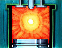
Fig. 52

NEVER OPERATE A DIESEL ENGINE WITHOUT A
GOVERNOR CONTROLLING IT.

Fig. 53

At this point, we have built up the basic diesel mechanical governor.
This governor works fine on engines whose engine speed is held
fairly constant and the governor is controlled by hand. However, on
other engines, the force needed to compress the governor spring or
to move the rack -just operating the governor - could be very tiring
to the operator.

Fig. 54

With the servo-mechanical governor, the work operation of
compressing the governor spring is done with engine oil pressure.

Fig. 55

With the hydraulic governor, the work operation of moving the fuel
injection pump rack is done with engine oil pressure.
These governors are discussed in . . . .

Fig. 56

. . . . Meeting Guide 60, “Servo Mechanical Governors.”

Fig. 57